I haven’t been “active” recently (Thanks school!), but I’m about to start on a fun project that I’ll hopefully get to write a bunch about before school starts up again. I’m building a guitar amp! If you don’t care for technical mumbo-jumbo, skip ahead to the question at the end of the post or something.
I’m building a guitar amp head based on the Fender 5F1, 5F2, and/or 5F2A circuits. These are Class A single-ended 5W tube amps made in the late 50’s, sold under the names “Champ” and “Princeton”. Mine is based on a Champ from 1958. Here’s a block diagram:
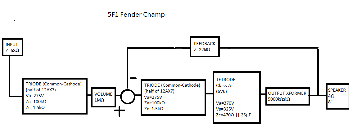
The 5F2 adds a simple low-pass tone control after the volume. The 5F2A adds a bypass capacitor to the first triode’s cathode resistor. This gives a little extra gain and brightness.
Here’s a preliminary schematic from LTSpice. I’ve been running LOTS of simulations, lol.

Here is a list of features I’m adding to the 5F1:
- Switchable cathode bypass capacitors
- Adjustable negative feedback
- Tone control
- Speaker impedance selection
- Output transformer open-circuit protection
- Adjustable preamp anode voltage
- Adjustable power tube voltages (probably not!)
Also I’m going to be using a solid state rectifier instead of a tube rectifier, but some might have a point of contention with me calling that a “feature”.
So let’s go through those. First, switchable bypass capacitors. I’m adding a switch to select between two different bypass caps for both triode’s cathode resistors. The 5F2A uses 25μF, which is overkill. Mine will have the option of no bypass, 2.2μF, or 0.22μF: The lower value will give a more distinct treble boost without boosting the overall gain too much. The boost from the 2.2μF option isn’t much different to the 25μF. Using the first stage’s boost should result in more triode distortion, while using the second stage’s boost should result in more distortion from the power tube. I hypothesize that since the power amp is Class A this shouldn’t be a dramatic distinction, but it should be noticeable. However, this is before negative feedback is taken into account. The second triode’s bypass cap effectively removes all negative feedback from the circuit.
Second, adjustable negative feedback. In these amps, there is a 22k resistor tied all the way between the speaker output and the second triode’s cathode. There is very little current through it but just enough to give the sound a little extra clarity. Of course, this reduces distortion, so some people like to remove it. I figure making it variable from 10k to 100k would be more interesting. There should also be a different effect depending on which speaker impedance is being used, and as mentioned above, any feedback at all has less effect if the second triode’s cathode resistor is bypassed.
Third, tone control. I’m considering using the 5F2 tone control as-is. If I wanted to create more work for myself I might use the Baxandall tone stack, which I have some affection for, but honestly it’s probably too much work for little payoff. The way I play my amp now is either dimed or with the highs rolled back, so I might as well be using a basic LPF like the 5F2 anyway.
Fourth, the output transformer I acquired has taps for 16, 8, or 4 ohms. I should either make the taps switchable or use separate jacks.
Fifth, output transformers hate being run without a speaker hooked up. Since I’m building a head instead of a combo, I should really design some kind of protection. Putting 220Ω from the 16Ω tap to ground should prevent say… a fire, but if I want even better protection I should find out what kinds of shunt diodes or MOVs or whatever else are out there. There is probably a jack available that switches to a dummy load when unplugged as well. Who knows if such things are trustworthy–more research is required.
Sixth, the triode plates are run at 275V. This can be decreased as much as I want without anything bad happening. In general, lower voltages sound bad but they give one the option of increasing distortion without increasing volume. Who knows, perhaps there will be an undiscovered sweet spot.
Seventh, the same as the above could be applied to the power amp tube. Unfortunately, it draws significantly higher current, and for safety, one shouldn’t change the plate voltage without changing the screen grid voltage as well. So while the triode voltage mod can be done with a single potentiometer, the power amp voltage mod would require the design of some kind of power BJT or MOSFET circuit. I’ve attempted to design a few of these that should work, but the parts are relatively expensive and I really doubt the work would pay off.
The biggest change I’m making isn’t an addition, it’s a substitution: silicon diodes instead of a rectifier tube. Some people claim that tube rectifiers sound better because they “sag” and others claim that they promote tube longevity because they take longer to turn on. Either of these design goals can be achieved via resistor and capacitor selection, so it’s kind of a non-issue.
So there, that’s a description of my goals. I need to come up with a task list so I guess I’ll do that right now. (Not including research. For me, research seems to just HAPPEN. I have something like 45 open tabs in Chrome, and that’s only on my phone…)
- Test power transformer with multimeter
- Test output transformer with multimeter, dummy loads
- Design solid state power circuit
- Make list of special parts needed–power resistors, HV caps, etc
- Determine cable current requirements
- Order passive components (digikey)
- Order tube sockets, tubes, chassis, board (ebay)
- Build power circuit
- Test power circuit
- Build amp circuit
- Populate chassis
- Test bias voltages
- Rewire old combo as cabinet
- Test amp with guitar
- Do some cabinetry
- Mount chassis in cabinet
I might have left something out…
I already started writing a post (which actually became this post instead) about the power circuit design, but it needs some work before it’s readable.
So yeah, that’s what I’ve been thinking about recently. Have any of you DIY-guys ever built a guitar amp? If any of you non-DIY guys have a guitar amp, what do you like about it?
